XHGG501XLokalizator uszkodzeń kabli
Zaawansowany lokalizator uszkodzeń kabli wyposażony w technologię reflektometrii w dziedzinie czasu (TDR) do precyzyjnego testowania odległości miejsca uszkodzenia z wiodącą w branży rozdzielczością minimalną 0,1 m.
Ten tester uszkodzeń kabli realizuje oddzielne próbkowanie kabla trójfazowego ABC, a kształt fali próbkowania jest jednocześnie wyświetlany na ekranie, dzięki czemu można porównać kształt fali kabla trójfazowego. Przyrząd posiada funkcje adaptacyjnej prędkości próbkowania impulsów wyjściowych i automatycznej analizy kształtu fali, a aplikacja jest prosta.
Charakterystyka produktu
| Maksymalna długość testu | nie mniej niż 50 km |
| Prędkość próbkowania | 10 MHz, 20 MHz, 50 MHz, 100 MHz, 200 MHz |
| Szerokość impulsu | 1us, 0,75us, 0,5us, 0,2us, 0,1us |
| Amplituda impulsu | 400 V |
- Technologia reflektometrii w dziedzinie czasu (TDR).
- Precyzyjna lokalizacja uszkodzeń kabli
 Możliwość testowania na odległość
- Minimalna rozdzielczość 0,1 m
- Inteligentna funkcja diagnostyczna
Zasada działania
Tester uszkodzeń kabli przyjmuje zasadę badania metodą fali bieżącej:
1. Metoda fali bieżącej: Gdy fala radiowa jest transmitowana w linii przesyłowej, jeśli linia przesyłowa nie jest jednolita, to znaczy zmienia się impedancja charakterystyczna punktu w linii przesyłowej, gdy fala radiowa jest przesyłana do tego punktu, oprócz dalszego przesyłania do obciążenia, spowoduje to również transmisję zwrotną i powrót do końca testowego, nazywamy transmisją zwrotną fali odbitej fali, zjawisko transmisji zwrotnej wytwarzającej falę nazywa się zjawiskiem odbicia fali. Tak zwana fala podróżna odnosi się do ogólnej nazwy fali padającej i fali odbitej.
2, gdy fala radiowa jest transmitowana w linii przesyłowej, polaryzacja echa w miejscu zwarcia jest przeciwna do polaryzacji emitowanego impulsu, a polaryzacja echa w punkcie załamania (w tym na końcówce kabla) jest taka sama jak polaryzacja emitowanego impulsu. Stosując metodę impulsową, przyrząd może z łatwością określić odległość między punktem uszkodzenia a końcem testu w zależności od polaryzacji echa.
3. Tester uszkodzeń kabli przykłada do testowanego kabla sygnał impulsowy o niskim napięciu, a sygnał impulsowy generuje sygnał odbity przez punkt uszkodzenia kabla. Tester uszkodzeń kabli przetwarza odbity sygnał i przedstawia wykres przebiegu. Grubą odległość uszkodzenia testowanego kabla określa się poprzez analizę odbitego kształtu fali.
Metoda okablowania jest następująca: Użyj pojedynczej linii Q, aby połączyć „interfejs próbkowania” testera uszkodzeń kabla z wadliwą linią fazową i warstwą ekranującą kabla. Okablowanie impulsowe niskiego napięcia pokazano na poniższym rysunku.
Uwaga: Podczas testu należy potwierdzić, że w korpusie kabla nie gromadzi się prąd.
Krok 1: Przymocuj linię sygnałową do fazy testowej A. Wybór fazy testowej odpowiedniego interfejsu jest również ustawiony na fazę A. Następnie kliknij przycisk próbkuj/zachowaj na interfejsie, aby przejść do stanu próbkowania. Obserwuj przebieg próbkowania. Jeśli myślisz, że sprzebieg wzmacniający jest dobry, kliknij przycisk próbkuj/zachowaj, aby przejść do stanu wstrzymania w celu analizy przebiegu. Patrz przykład „przebiegu”.-Analizuj przebiegi.
Krok 2: Przymocuj linię sygnałową do fazy testowej B. Powtórz pierwszy krok procesu testowego.
Krok 3: Przymocuj linię sygnałową do fazy testowej C. Powtórz pierwszy krok procesu testowego.
Po zakończeniu powyższego trzyetapowego testu interfejs wyświetla jednocześnie przebiegi testu impulsowego kabla trójfazowego.

 Twoja wiadomość musi mieć od 20 do 3000 znaków!
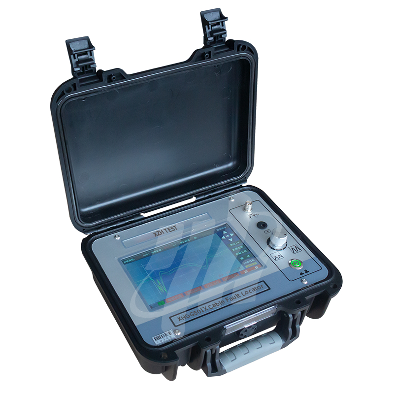
Ogólna ocena
Przegląd ocen
Poniżej znajduje się rozkład wszystkich ocenWszystkie recenzje